


Quickstart manual for SCR-485,step by step tutorial
Device Power-Up
Input: Connect 220V voltage input
Output: Connect to the resistive load, such as the heater of the tank boiler.
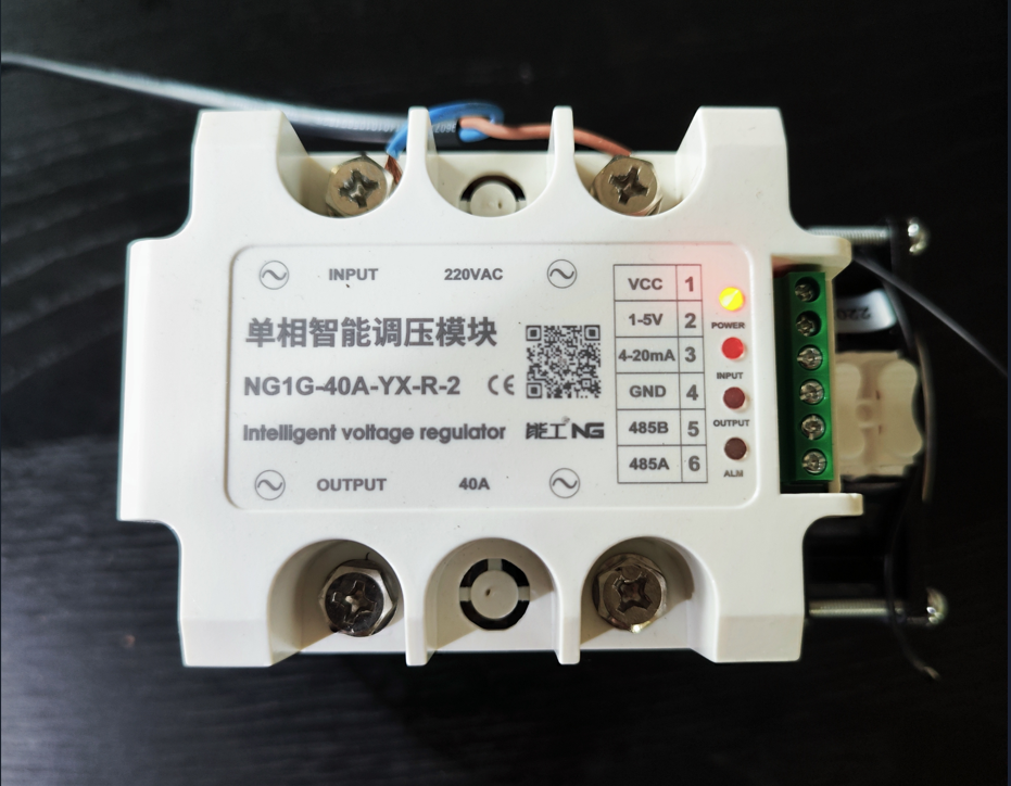
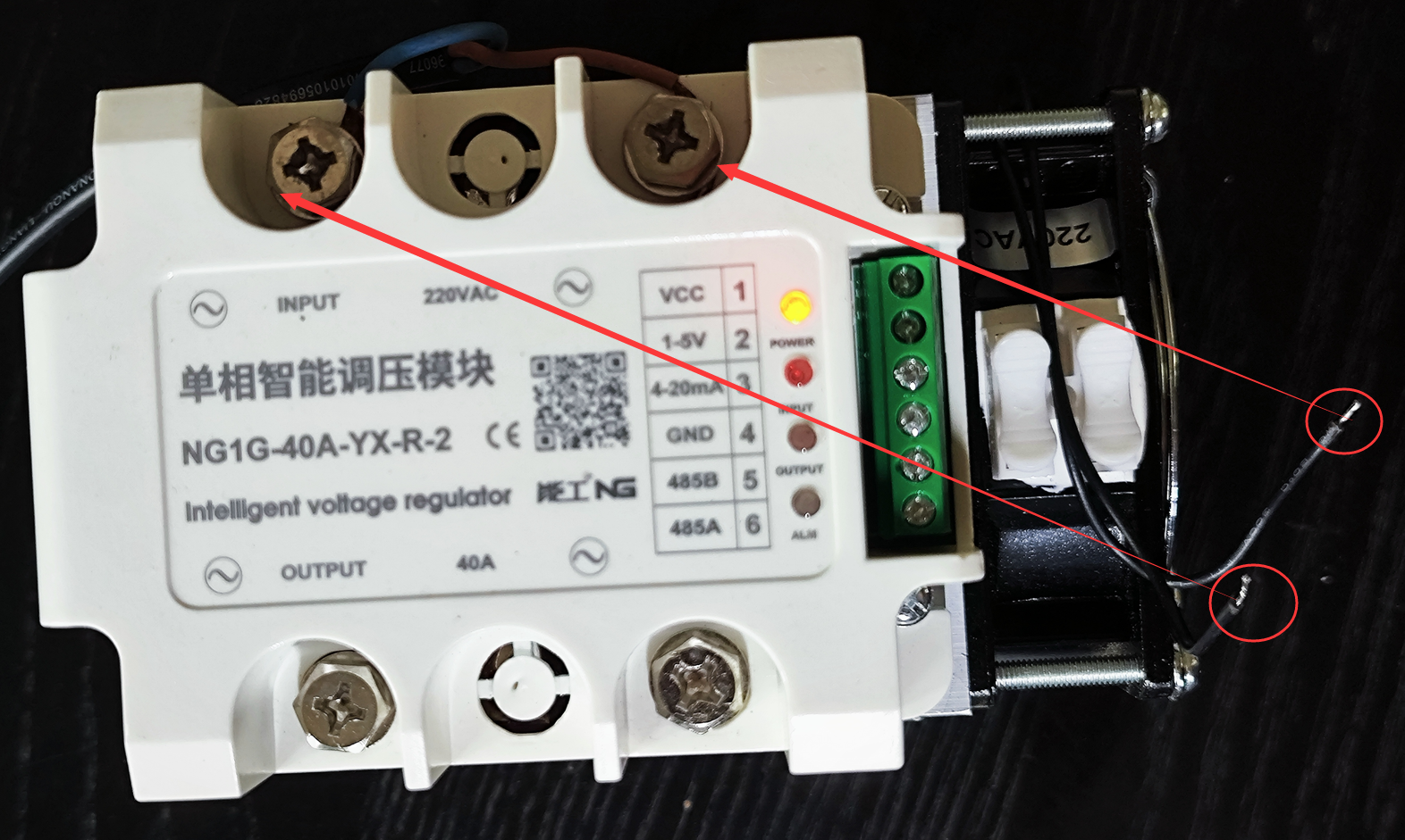
FAN Power Supply: The fan requires 220V power supply, directly connected to the input voltage.
ESPHome
Installing ESPHome
If you have already installed Home Assistant, you can add the ESPHome add-on within Home Assistant. We will introduce how to add and edit SCR-485 devices in Home Assistant in another document.
If you are not familiar with Home Assistant, you can install ESPHome directly. Refer to the link below.
https://esphome.io/guides/installing_esphome
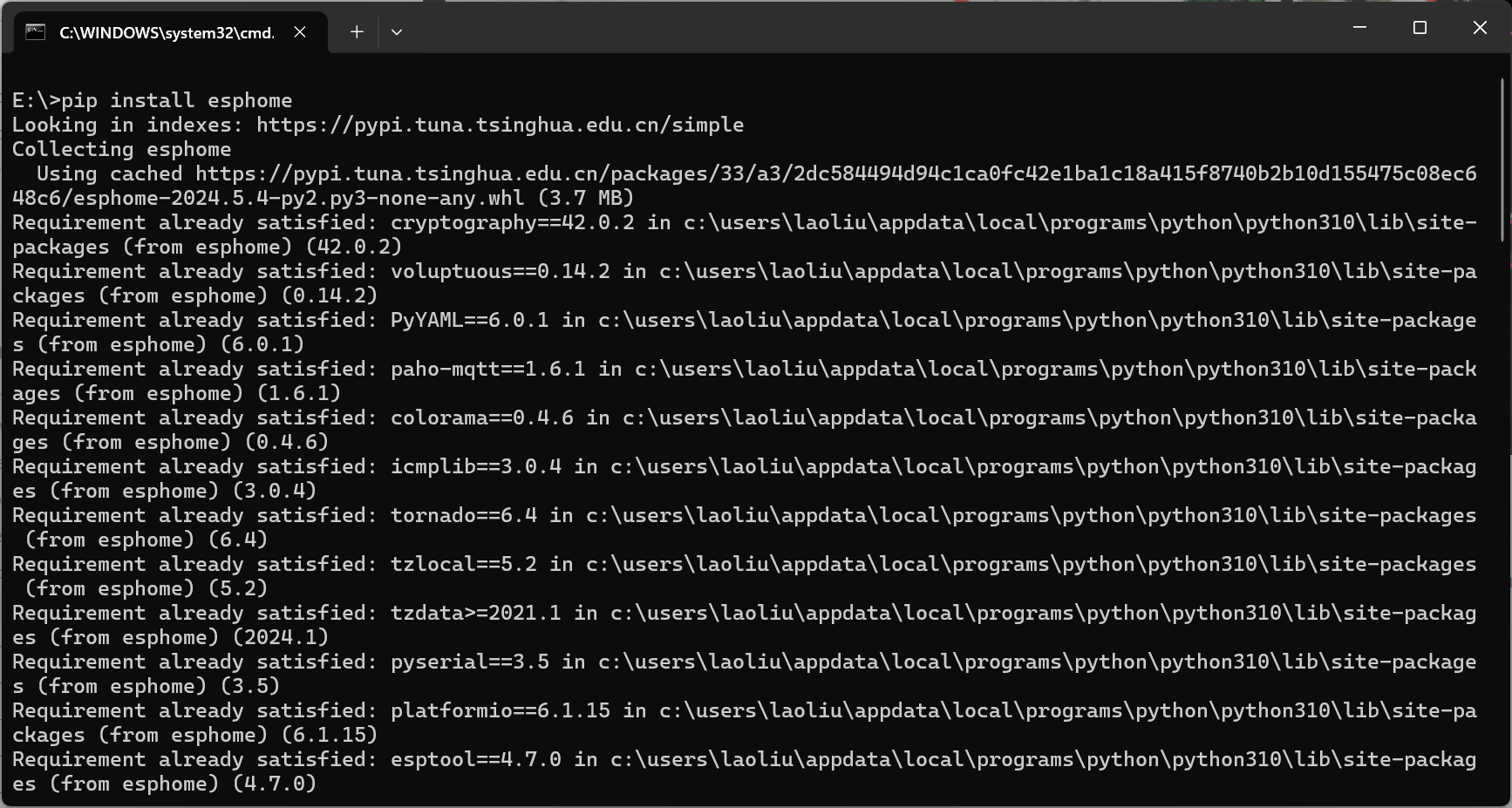
If you have already installed Python, the whole process is very simple, just one command:
pip install esphome
Running ESPHome
We choose to use ESPHome in dashboard mode. If you are using a Windows system, the steps are as follows:
- Enter cmd (please do not use PowerShell).
- Create a folder named esphome_config (name is arbitrary, but will be used in the command below).
- Run
esphome dashboard esphome_config.
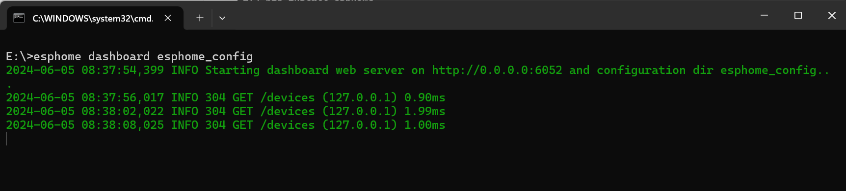
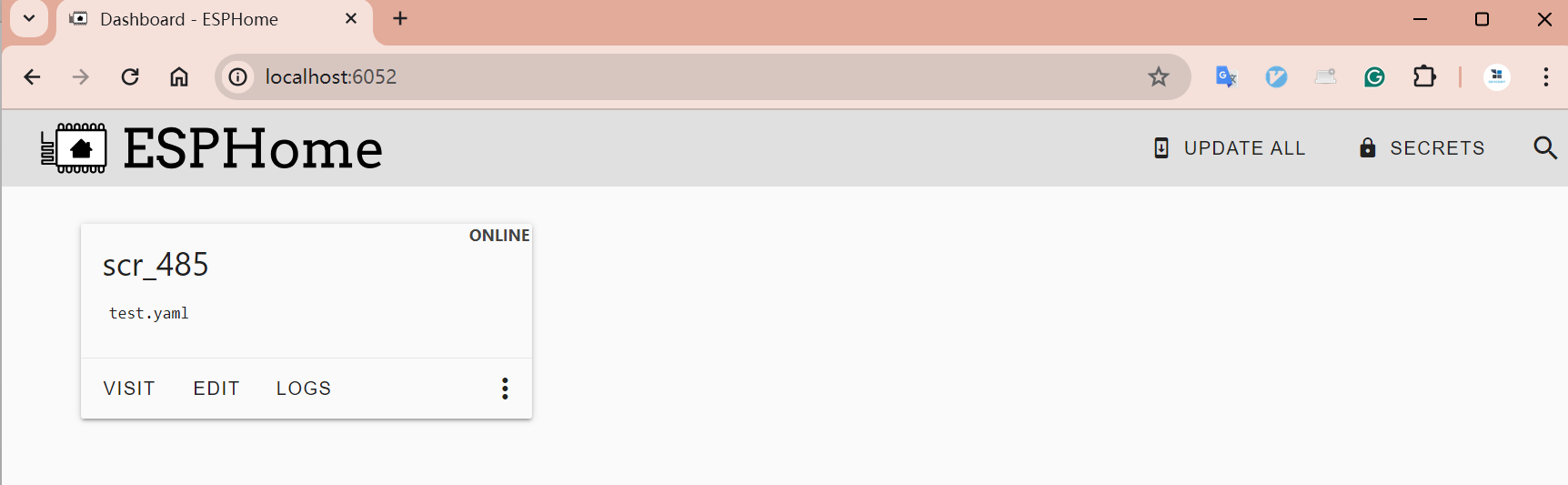
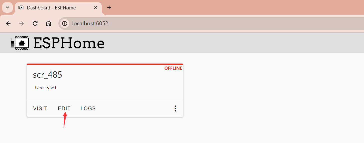
- Access http://localhost:6052/, and you will see the following page.
If you are using other systems, the method is similar; please search on your own.
Updating YAML Files
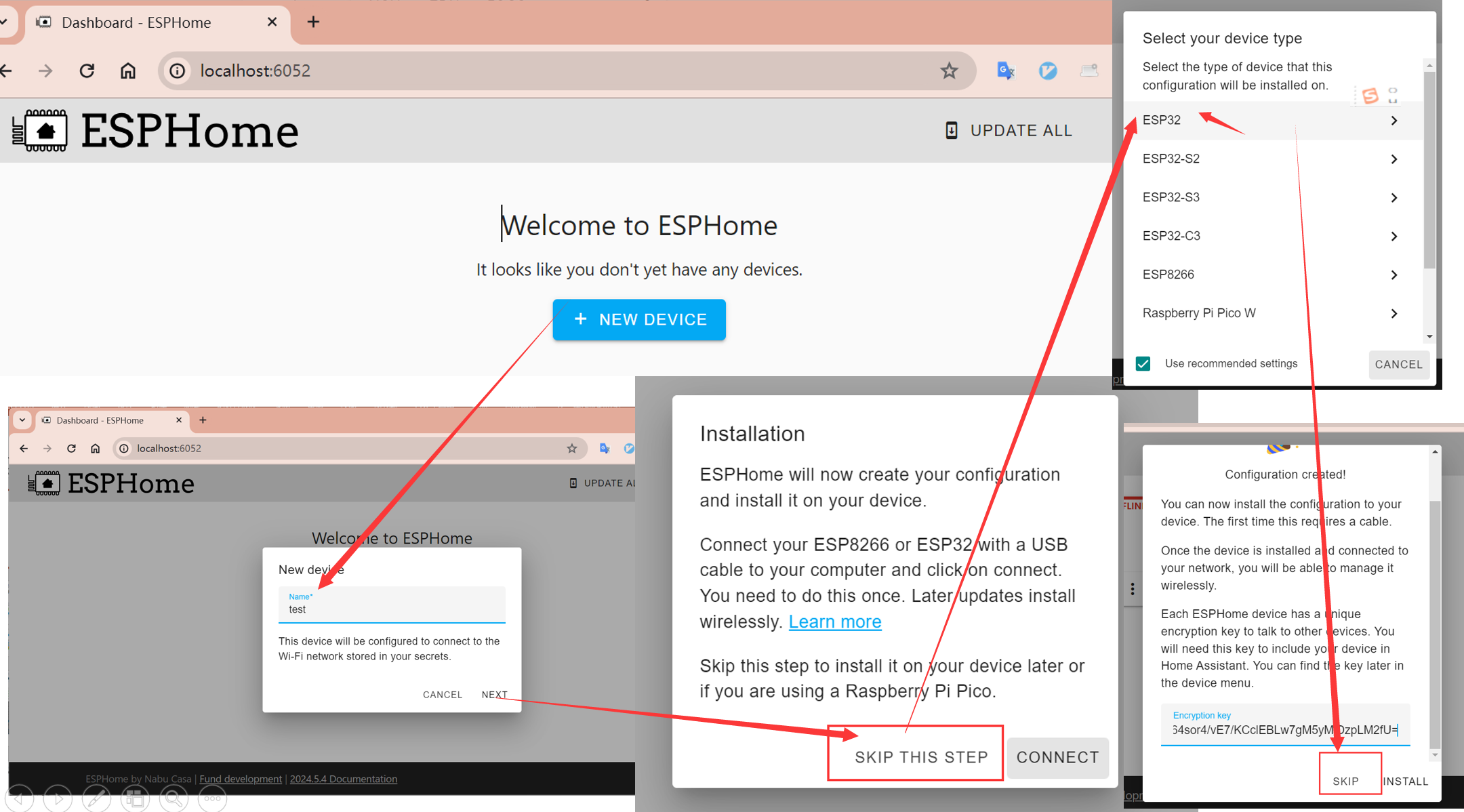
- Access http://localhost:6052/. The first time, you need to add a device as shown in the following image:
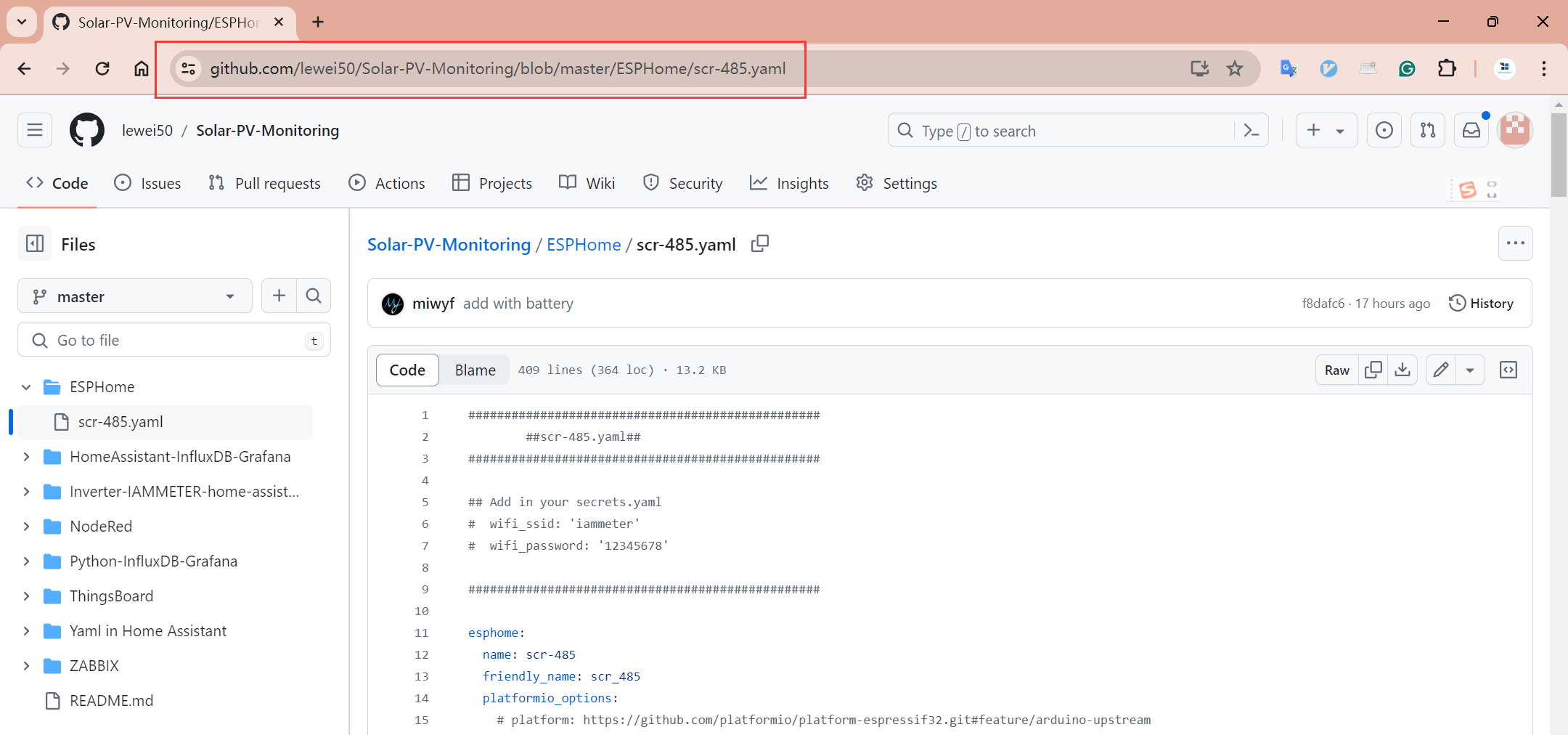
- Get the latest YAML file from https://github.com/lewei50/Solar-PV-Monitoring/blob/master/ESPHome/scr-485.yaml
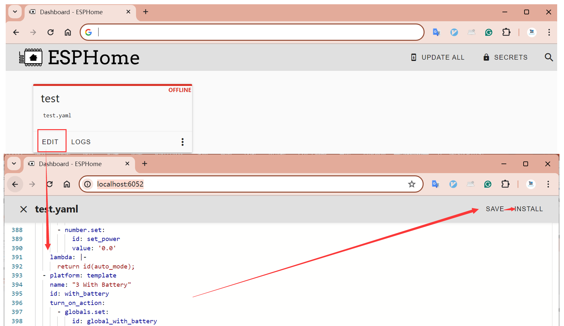
- Click edit, copy the latest YAML file into it. Click Save, then Install.
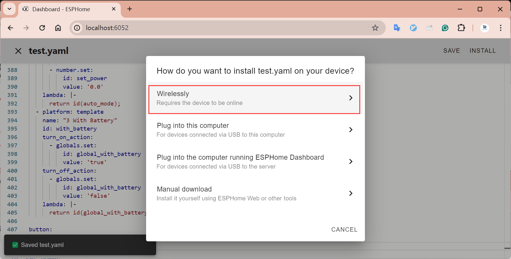
- After clicking "Install," a menu will pop up, select "Wirelessly".
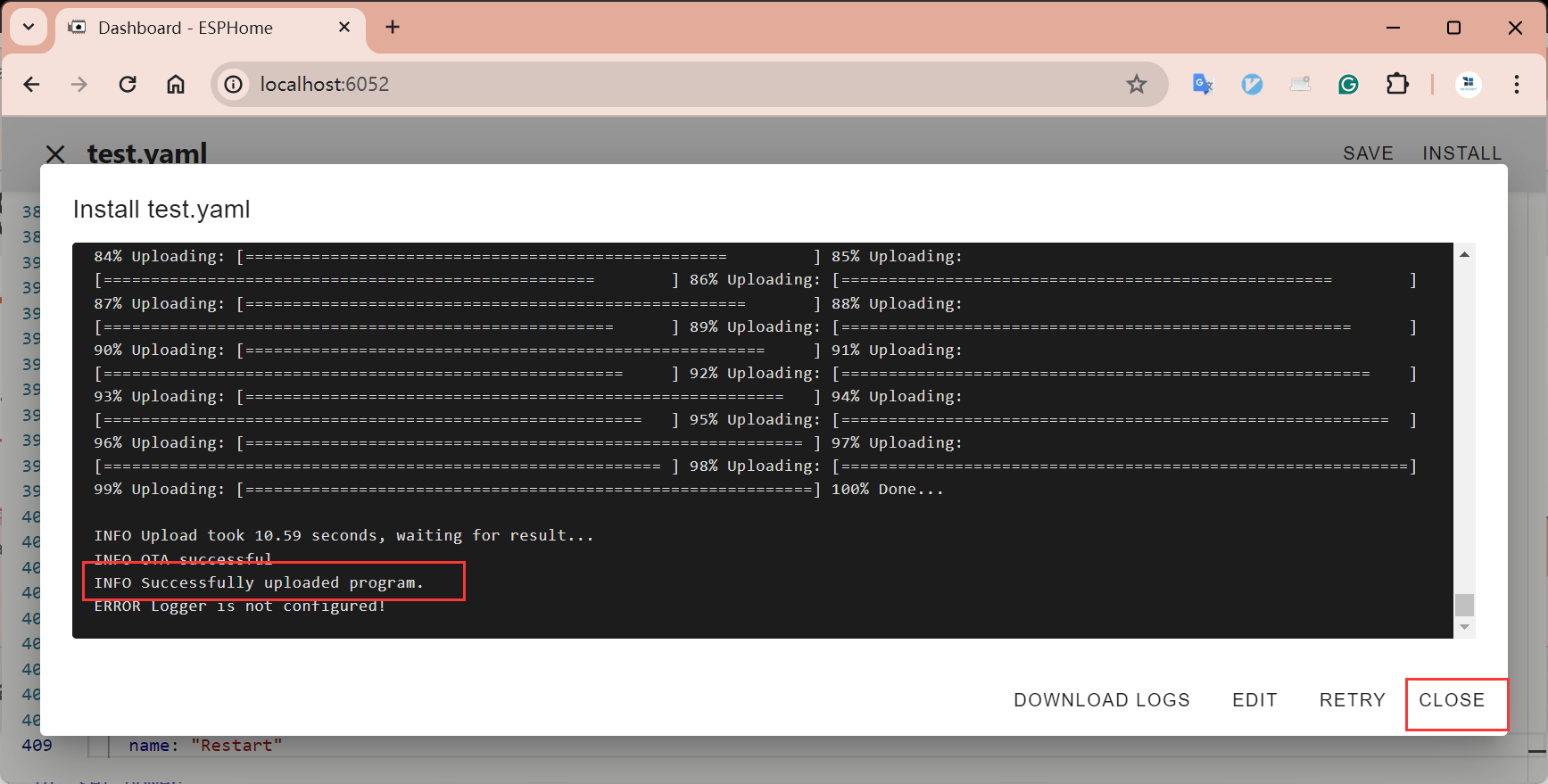
- Wait for the upload to complete, then click "Close".
Using SCR-485
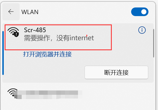
Configuring WLAN
- Search for the WLAN AP, link to Scr-485.
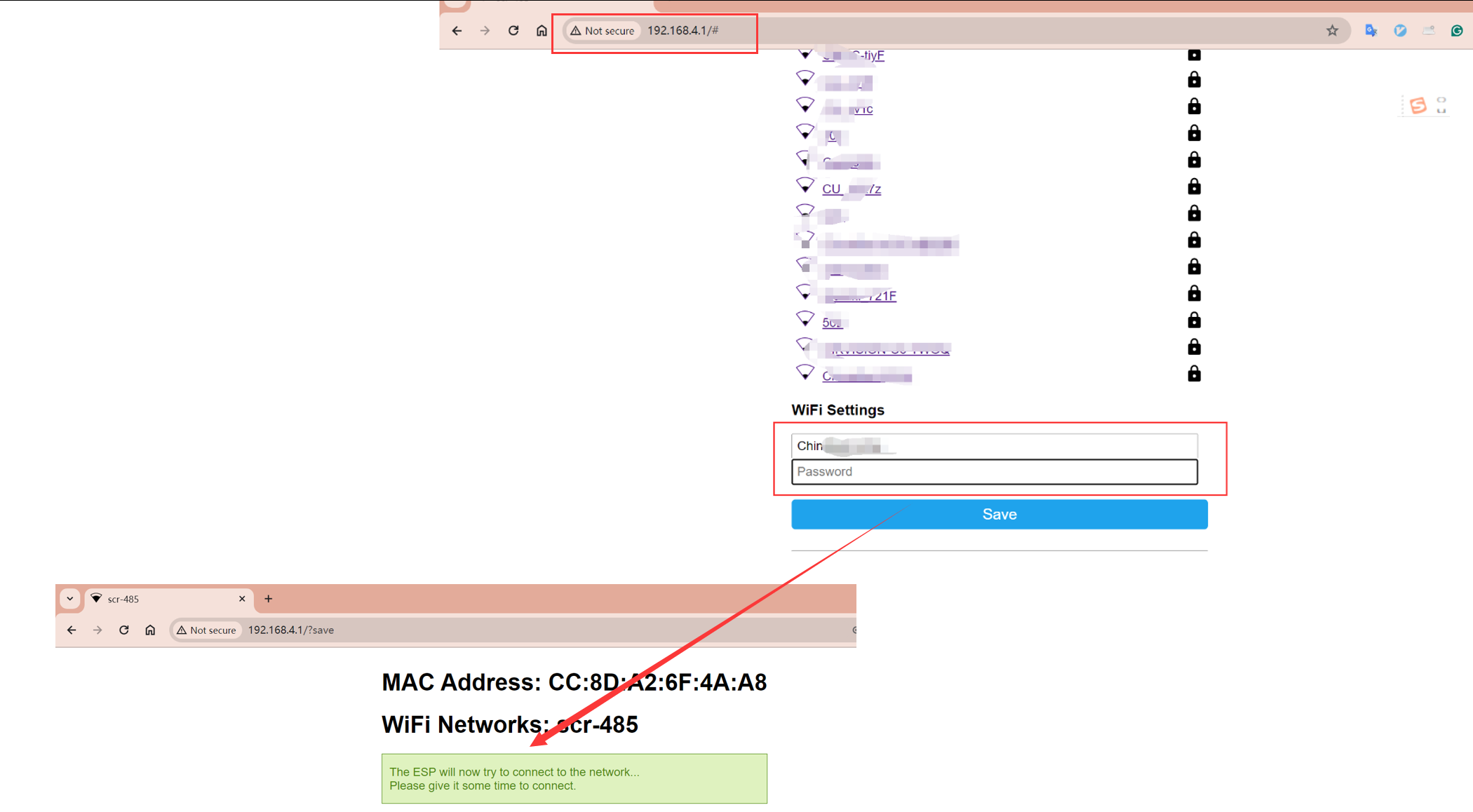
- Enter the WLAN's SSID and password, then click Save.
Parameter List
Access http://scr-485.local/ to directly set related parameters
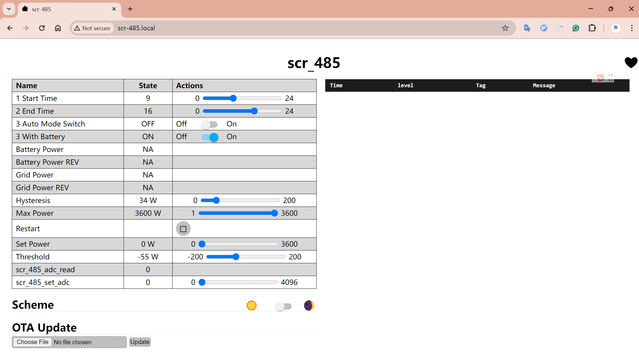
Parameter list:
| Name | Comment |
|---|---|
| 1 Start Time | Set: Automatic mode start time (only effective when automatic mode is on) |
| 2 End Time | Set: Automatic mode end time (only effective when automatic mode is on) |
| 3 Auto Mode Switch | Set: Automatic mode switch, turns on to automatically adjust power output based on grid power |
| 3 With Battery | Set: Indicates if the system has a battery, turns on to adjust power output based on grid power and battery power (only effective in automatic mode) |
| Battery Power | Display value: Battery power |
| Grid Power | Display value: Grid power |
| Hysteresis | Set: Automatic control hysteresis value (only effective in automatic mode) |
| Max Power | Set the maximum power load (if the maximum power load is 3600W, this needs to be set to 3600) |
| Restart | |
| Set Power | Set: Current set power of SCR-485 |
| Threshold | Set: Automatic mode set point power (only effective in automatic mode) |
| scr_485_adc_read | Display value |
| scr_485_set_adc | Display value |
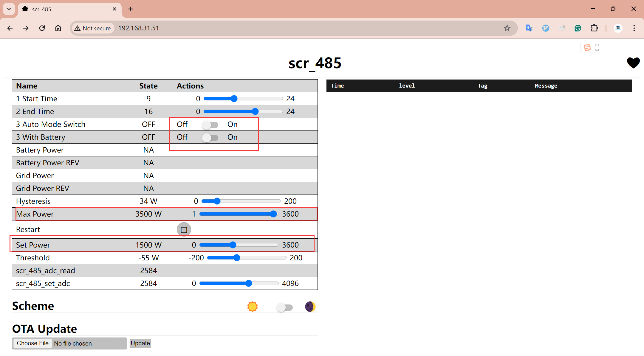
Example 1: Manually Controlling Boiler Heater Power
Starting from a simple example, suppose you have a boiler heater with a maximum power of 3.5 kW, and you want to limit its set power to 1500W using SCR-485.
You just need to do the following:
- Set "Auto Mode Switch" and "With Battery" to "off".
- Set "Max Power" to 3500.
- Set "Set Power" to 1500.
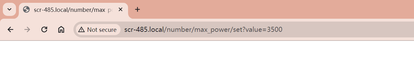
Of course, you might find it difficult to set precise values by dragging on the webpage. So, you could consider setting via API API of ESPHome
Invoke the following addresses through HTTP Get:
http://scr-485.local/number/max_power/set?value=3500
http://scr-485.local/number/set_power/set?value=1500
Example 2: Controlling Boiler Heater Power Based on Grid Power
This example is a bit more complex as it requires specifying the source of grid power. It boils down to three steps:
- Clarify the source of grid power.
- Access http://localhost:6052/ to modify the YAML file and upload to SCR-485.
- Access http://scr-485.local/ to set parameters.
How to Obtain Grid Power
Here, we use the IAMMETER series of meters as an example, because the IAMMETER energy meters provide this API MonitorJson API, allowing SCR-485 to obtain real-time power readings via this API.
Modifying the YAML File
Due to ESPHome functionality limitations, it's not possible to set the source of grid power from the front-end page; it can only be achieved by modifying the YAML file (if you know a way to accomplish this, please let us know).
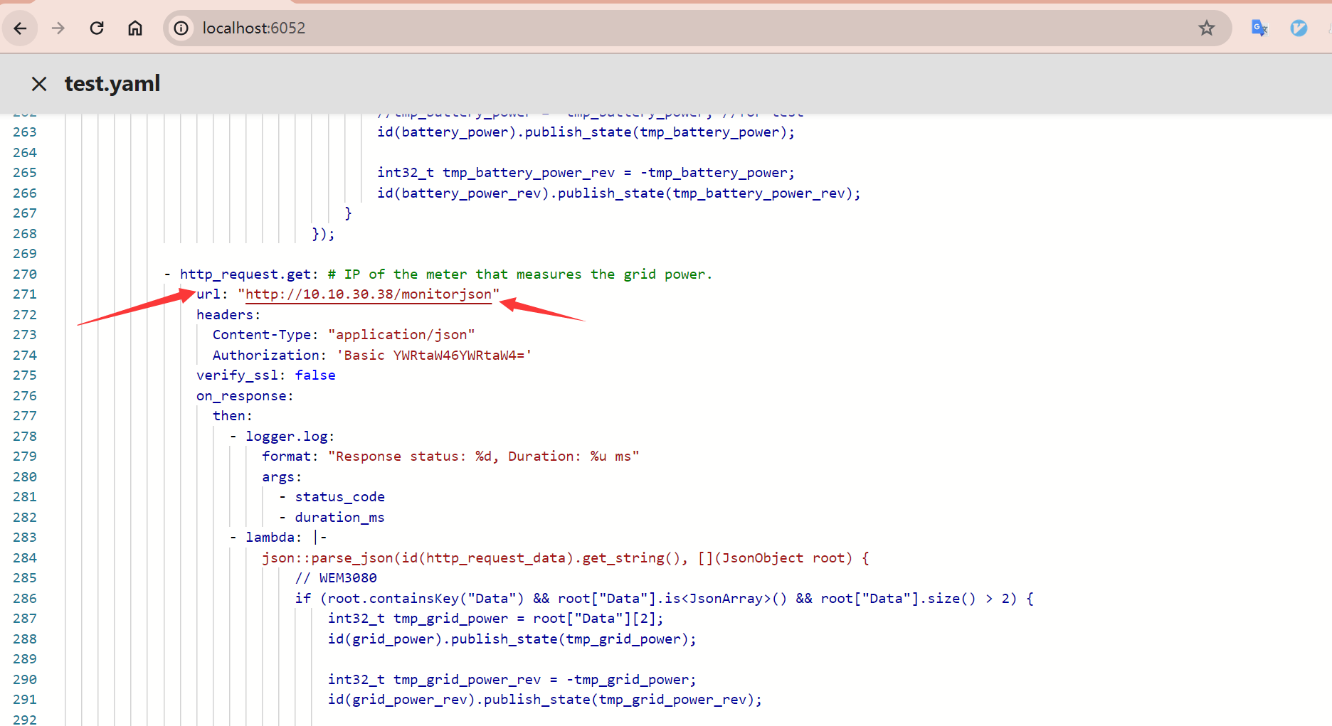
Log into the ESPHome Dashboard and click "Edit"
Modify the IP address, enter the IP of the meter measuring grid power here.
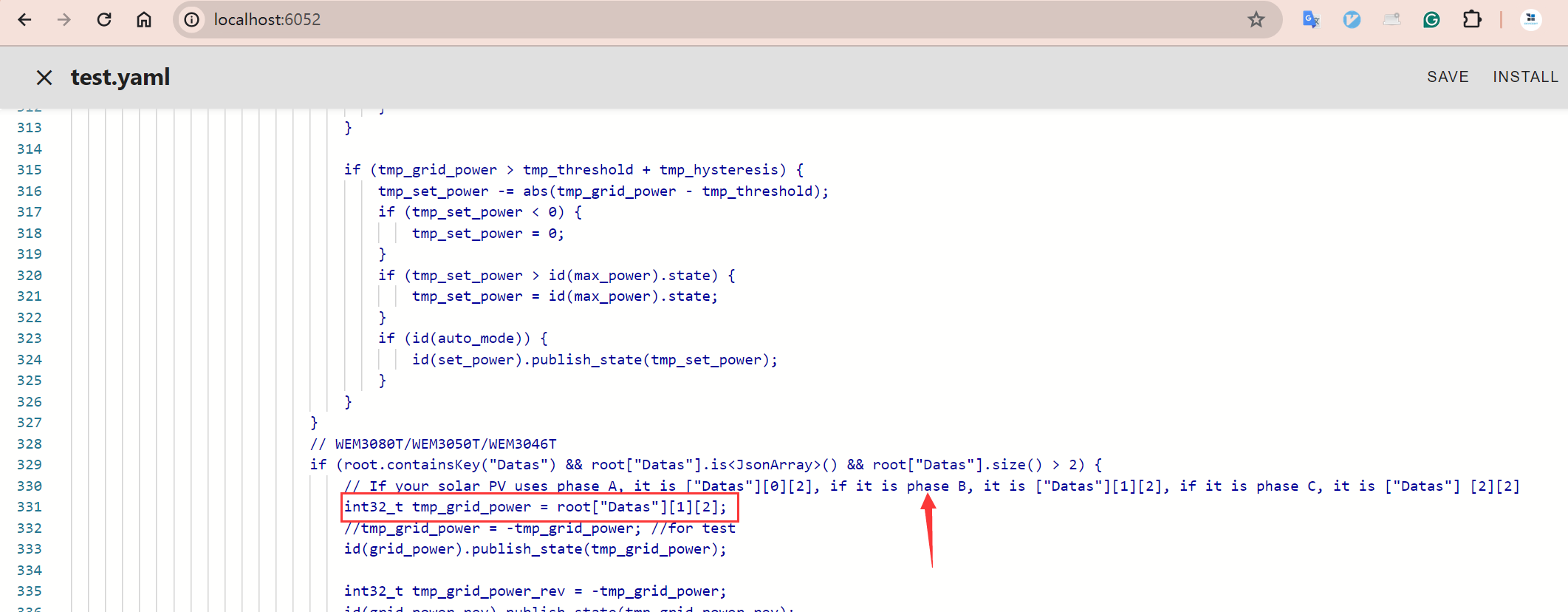
If using a three-phase meter to measure grid power, specify the corresponding phase in the YAML.
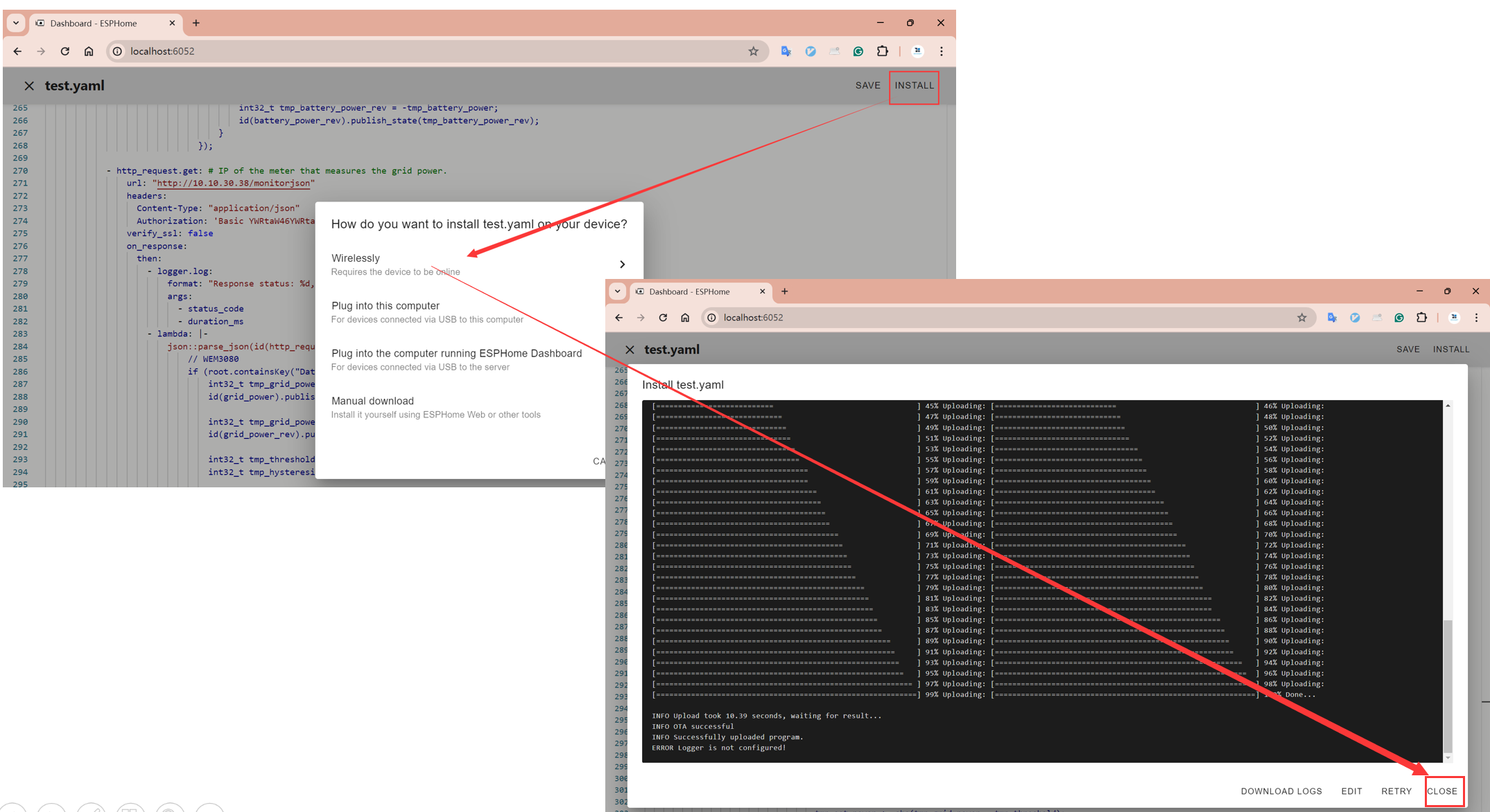
Click the top right "save", "Install", "Wirelessly", wait for the end, then click "Close"
Please note: After each modification and upload of YAML, you need to reconfigure the Wi-Fi parameters of SCR-485 (reconnect to the Scr-485 AP)
Access http://scr-485.local/ to set parameters
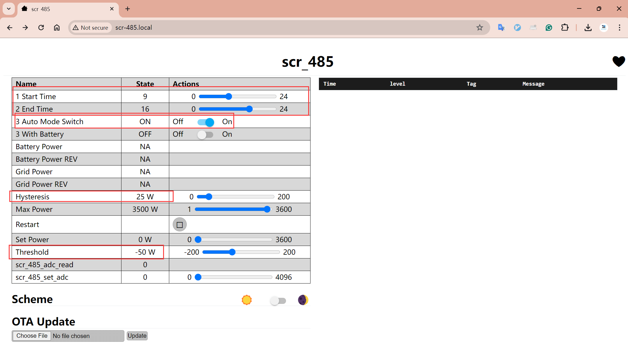
If you cannot set precise parameters by dragging, you can directly call the following two APIs to complete the settings:
http://scr-485.local/number/threshold/set?value=-50
http://scr-485.local/number/hysteresis/set?value=25
The settings shown in the above image are equivalent to the following strategy:
- Turn on automatic mode
- Set the control point power to -50W (negative grid power represents power feeding to the grid, positive grid power represents power consumption from the grid), hysteresis at 25W
- This automatic strategy is effective from 9 am to 4 pm every day.
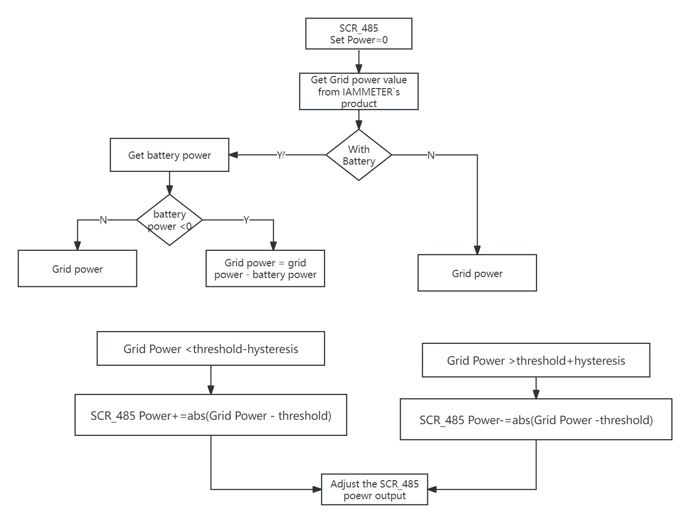
That is, when grid power is greater than -25W (threshold+hysteresis), SCR-485 will reduce power output, the reduction amount being grid power - threshold.
When grid power is less than -75W (threshold-hysteresis), SCR-485 will increase power output, the increase amount being threshold-grid power.
Automatic Control Logic
This is the entire device's automatic control logic diagram, using the most basic high-low level control logic. If interested, you can learn more. If you have better ideas, feel free to discuss at https://imeter.club/
References
Activities - Apply for the Linear Power Controller (SCR-485)
Control a boiler heater using a Wi-Fi SCR module automatically
ESP32 + SCR module: Linearly adjust the power output of resistive loads, such as heaters
A smart Thermostat “Helper” with Linear Power Adjustment, “Wi-Fi Voltage Controller”


")
")